UMA-1500 – Manipulator

product

Specifications

  • Number of axes:

    6 *

  • Lenght:

    2 meter *

  • Weight in air:

    28 kg (61.8 lbs) *

  • Weight in water:

    14 kg (30.9 lbs) *

  • Max depth:

    1500 msw

  • Lifting capabilities:

    10 kg (22 lbs) in air *

  • Control System:

    Embedded servo-boards with joint-level control at 200 Hz

  • Sensors:

    Joint position with high resolution, 6-axis force/torque on the wrist (optional), camera on the wrist (optional)

  • Power:

    24 Volt, 200-500 Watt (depending on number of active motors)

* The physical characteristics of every manipulator are dependent on the selections made by the user in terms of number of axis and sizes. Data in the table are reported just as an example and refer to the arm in the picture (without the terminating gripper)

introduction

What is UMA

As the name suggests, UMA is an underwater robotic manipulator, designed by adopting a modular approach. Its composing elements, the basic modules, are made of Ergal, a special aluminium alloy exhibiting favorable properties in terms of high fatigue strenght, light weight and easy machinability.

All the robot motions are generated by brushless motors that are driven by servo boards located inside the structure. The presence of an embedded distributed control layer strongly facilitates all the operations of insertion, removal, substitution of basic modules.

The intrinsic flexibility descending from the modular design and the easy integration of the manipulator on board of supporting vehicles make UMA a versatile robotic platform, capable of executing a wide range of manipulation tasks within applications in the fields of O&G, Defence & Security, Oceanography and Environmental Monitoring.

Modular Approach

UMA design has been performed by adopting a modular approach. Two types of basic modules have been conceived: the joints, providing mobility to the structure, and the links, the rigid bodies interconnecting the joints.

All the manipulator motions are generated by electrical brushless motors, integrated inside the joints. Every joint contains either one or two motors, thus providing one or two degrees of freedom. Both the single-motor and the dual-motor joints are available with multiple sizes and with different mechanical transmission ratios, in order to meet the user needs in terms of desired motion speed and torque capability.

All the joints share the same mechatronic interface on both their terminations. In this way, by just varying their number or dimensions, or by changing the shape or lenght of links, or the order the basic modules are interconnected, different manipulators can be easily obtained.

Embedded Distributed Control

Inside the joints, embedded servo boards provide low-level control functionalities to the motors, through position, speed and current control loops. Every board drives a single actuator, so the dual-motor joint has two embedded servos, one for each motor.

All the boards of a manipulator are interconnected through a common CAN-bus data link, providing a unique interface for sending motion commands to every joint and receiving feedback information at a rate of up to 200Hz.

Easy integration

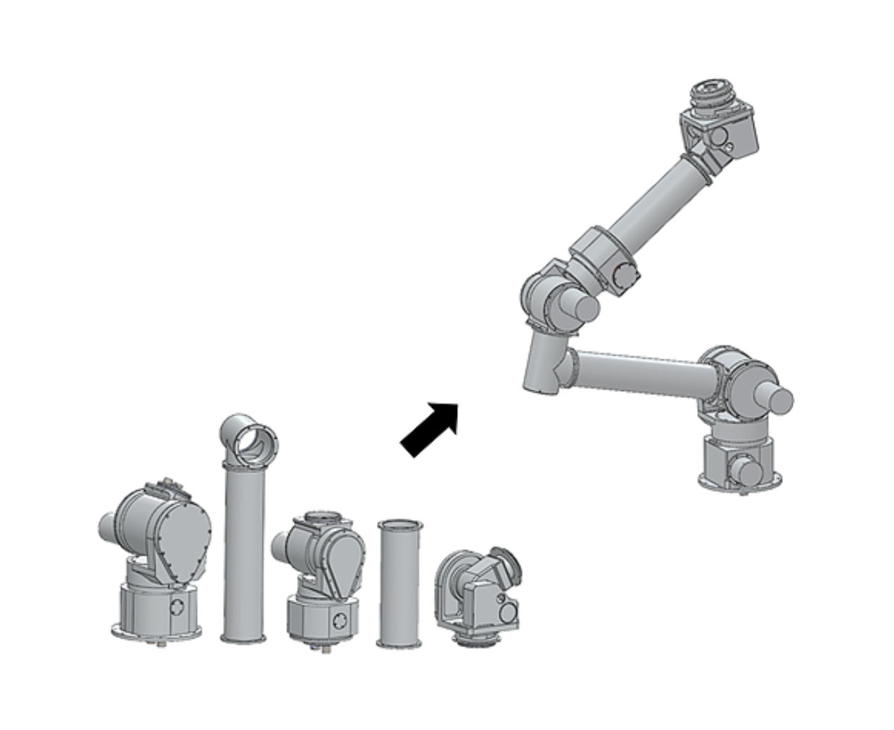
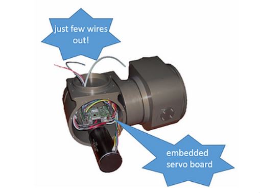
The presence of an embedded distributed architecture, other than reducing the cabling issues, strongly simplifies the integration of modules, as it allows standardized mechatronic interfaces.

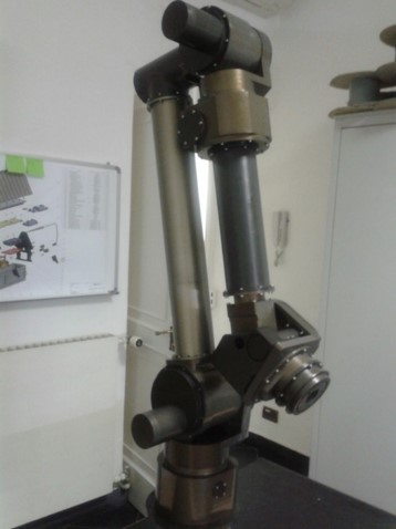
On the two terminating flanges of every joint, just two electrical connectors are used for establishing power and data links with all the other joints, through electrical cables running inside the links.

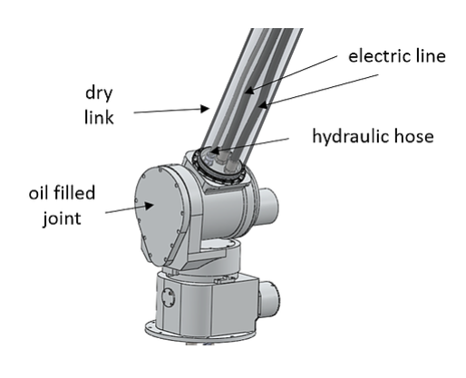
A third connector is also present for connecting all the joints through hydraulic hoses and establishing a global hydraulic circuit, running from the base to the wrist of the manipulator. In this way, whenever the considered application requires a strong depth compliance, all the joints can be easily filled by oil, while maintaining the links dry and without dismounting the robot.

Also the integration of the manipulator with a supporting vehicle results extremely simplified, as it can be operated by simply connecting the two electrical connectors located at the base of the robot, to a power source and to a computer with a CAN interface, and the hydraulic connector to a pressure compensator.

Together with a common power line, the CAN-bus line is the only existing electrical connection shared by all the joints and running along the whole structure of the manipulator. All the other wires, like those from the motors and the joint sensors, remain inside the joints and are locally acquired and managed by the servo boards.